Overview
Measuring the intensity of an electric current may seem simple when you use any device that works well. But it was also quick to make a measurement error with a voltmeter wrong ... As with any measure, it is well known for its measuring device and to know its limits. There are several ways to measure a current:
- Intrusion (insertion) of the measuring circuit in the power
- By coupling electromagnetic current transformer style
- Hall effect
This page describes briefly the first two methods.
Measurement of current intrusion
This first method, recommended for low current or average value, is simple to implement for measuring a current flowing into an integer, but is more difficult to apply for the measurement of current flowing in a portion of mounting . It involves inserting a resistor of known value in series with the power, and measuring the voltage drop it causes.
Example
On the block diagram below, we see a circuit (represented by the blue rectangle) powered by a source voltage of 12V BAT (battery lead, for example). We would like to know the course I charged by the voltage source BAT, on the one hand to check that everything goes well, and partly to more precisely estimate the possible autonomy that can be expected of the system.
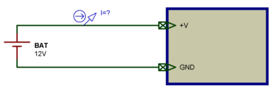
The insertion of an ammeter or a universal controller set to ammeter in series with the food, is the first idea that may come to mind, as shown below:
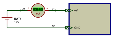
As may already have an order of magnitude of current drawn without knowing exactly the value (otherwise the question would be meaningless), the ammeter is placed on the gauge for measuring the most accurate possible. In this case it is the caliber 200 mA, the lowest in the device used. This requires opening the power circuit for the connection of the measuring device, which generally does not pose too much problem. But it may also prefer to put a measurement system to remain independent from the meter that can be used in a lot of other things. The idea is to insert a resistor in series with the power, in order to continuously measure the voltage developed at its terminals, as shown below.
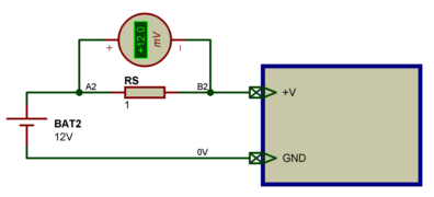
The measure now a unit "volt" or "millivolt" which requires the conversion unit "amperes" or "milliamp. Where previously it read 12 mA, it now reads 12 mV. The conversion unit is easy, as long as you know the phrase "U = R * I", which can easily derive the formula "I = U / R". The choice of the value of the series resistance RS seems evident, as giving the value of 1 ohm, the value of I is equal to the value of U: the value displayed in Volt corresponds exactly to the actual mA value: 12 mV displayed correspond to a current of 12 mA.
Miraculous!
Things are as simple as this: add a 1 ohm resistor in series with the feed assembly, and reading directly the voltage at its terminals, instantly assume the current drawn ... It is possible that this operation "universal" problem in some cases ... To get an idea of the results obtained in other contexts with the process very simple, look at the thing with two other circuits, one that consumes very little current (12 uA), and one that consumes much more (1.2 A).
1 ohm resistor with a circuit consumes 12 uA
In the previous circuit, we could assimilate the resistance of the power electronic circuit to a value close to 1 KO, since there was an intensity of 12 mA at a voltage of 12 V (ratio of absolute mile). RS added resistance of 1 ohm value was low compared to the internal resistance, and could be considered very little pertubative, even if it caused a small reduction of current consumption (a fall of about 0.1%). By measuring a consumption of 12 uA under a single source voltage of 12 V, it is reasonable to assume that the internal resistance of the circuit is close to 1 MB. RS shunt resistance of 1 ohm (the term shunt is often used to describe a low resistance value used for current measurement) placed on the course of food will have a more significant influence, and we can expect a value read more just. Lets look at it closely.
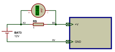
Ah ... the measured voltage is 0.01 mV, and the caliber of the voltmeter is the lowest you can have. We are therefore facing a lack of precision in the measurement itself. Because if the owner is well aware of 12 uA, we read a value of 10 uA: measurement error is 20%, a value totally unacceptable. The solution is to use a voltmeter to measure and display microvolts, which is not necessarily a simple solution for everyone. Another approach: increasing the value of the series resistance RS until the voltage chutée be used with a conventional voltmeter. In bringing this series resistance RS to a value of 1 KO, or 1000 times larger than the previous value, the voltage should be chutée thousand times larger ... in theory. Because obviously it's not quite true. By increasing the resistance in the power circuit, the current drawn is necessarily weakened. Everything is, as previously, not the affable little (compared to the current consumed in the absence of resistance) on the one hand not to disturb too far, but more importantly, not to disrupt the operation of the assembly itself. On the diagram below, we find our strength SR 1 KO, whose value is compared to 1 MB of internal resistance of the circuit.
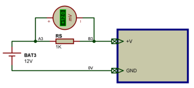
That's it. By adopting a value of 1 KO for RS, it is 12 mV corresponding to a value of 12 uA (I = U / R = 12 mV / 1 KO). The assembly operation is not disturbed, because the current drop caused by the addition of RS is 0.1% and can be considered negligible. The first conclusion to be drawn from this experience, the series resistance RS should have a low value against the resistance of the mounting power, while having a high enough voltage to develop easy to measure.
1 ohm resistor with a 1.2 A circuit consuming
What will happen now if you insert a resistance of 1 ohm RS, in the supply of a montage of a nominal current of 1.2 A? If the current through RS is 1.2 A, it should in theory have a voltage drop of 1.2 V at its terminals. The assembly will be somewhat more power than under 10.8 V, but this should not pose a problem, is not it. Let the measure.
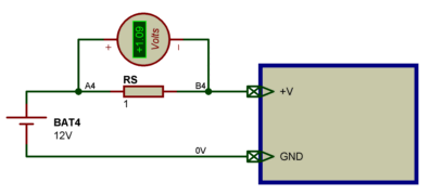
Oops ... 1.09 V at the terminals of the resistor RS. One might think that the assembly until a voltage of 12 V and who receives only 10.9 V not work perhaps not quite as expected: the current drawn is increased from 1.2 A to 1.09 A, approximately 10% less. RS and resistance, which dissipates a power of more than 1 W, chauffe much because the author's head was elsewhere and had chosen a 0.5 W. Without a high school (which is my case), we can conclude that the measurement method is not good. Or if the method itself is correct, the value given to RS would probably be revised. If we had the same reasoning as just now, we would have known that the internal resistance of the circuit is close to 10 ohms (1.2 to 12 V), and was found later that the value of RS n was not quite small in proportion. Therefore adopt as a moment ago a report about a thousandth, or RS value of 0.01 ohms (10 milli-ohms).
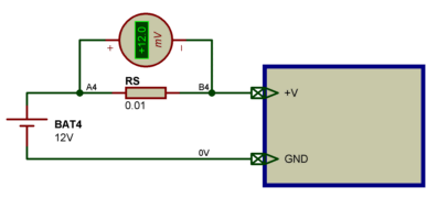
This time, we measure a voltage drop of 12 mV in the RS resistance of 0.01 ohm, which corresponds to a current of 1.2 A. The assembly is fed a loss of voltage of 12 mV, which is still more acceptable that a loss of 1.1 V. The conclusion can be drawn from this experience with that of previous experience: the value of the resistor RS must be much smaller than the resistance of the mounting power, so that the resulting voltage drop is limited to few mV. If one wishes to make measurements on a wide range of currents possible, use several different resistance values, for each class of measurement.
My dealer does not have a resistance of 0.01 ohm
Admittedly, a small resistance value is not as common as resistance to 1 or 47 KO KO. You can easily find the 0.1 ohm resistors (see photo below) but below it is more difficult.
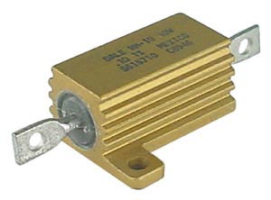
Because generally, the resistance of low value are not what you might think. It may indeed be a piece of track on a printed circuit board, a rigid piece of metal shaped tongue (long and flat) or bridge, or wire used for the resistive heaters ( Kanthal wire to 1 ohm per meter, for example).

In a test, it can also be a resistance "electronic" consisting of a power transistor providing a short circuit and frank ordered PWM (resistance to the terminals of the transistor can have a value that can be programmed).
Note: The values of resistivity of agenda milliohm also correspond to the residue of electrical contacts, the minimum values of certain power MOS transistors in passing mode. These are the ones we hunt (because we want to avoid or at least control or offset) in the mountains with high power consumption.
Making this measurement method by inserting a shunt resistance
001 analogue ammeter
002 analogue ammeter
Measurement of current coupling
This second method is perhaps more widely used for measuring strong currents, but it is also suitable for low currents of a few tens of microamperes (measurements of leakage current) or a few hundred mA. It makes use of current sensors or current transformers, which consist of a coil (single or multiple coils) through which we place the electrical conductor carrying the current to be measured.
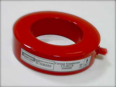
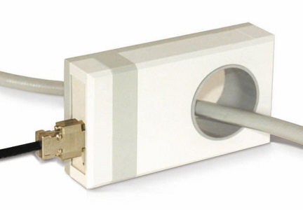
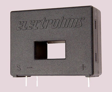
When the electrical conductor carrying the current to be measured is covered by a current, it creates around it a magnetic field that is sufficient to capture and convert voltage function performed by the coil and more or less associated electronics. When the driver in question can not be cut for the purpose of the measure, it needs to have a system where the measurement loop can be opened (for the setting up around the driver) and close (so far can take place). Such a system can be in the form of rigid cable electrical contact or as a clamp.
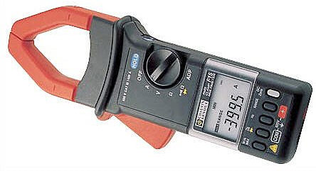
Pince ampermétrique
Measurement of current Hall effect
This type of measurement is based on the use of a Hall effect sensor, which produces a voltage which is a reflection of the current linear detected.
Aucun commentaire:
Enregistrer un commentaire